Your cart
There are no more items in your cart
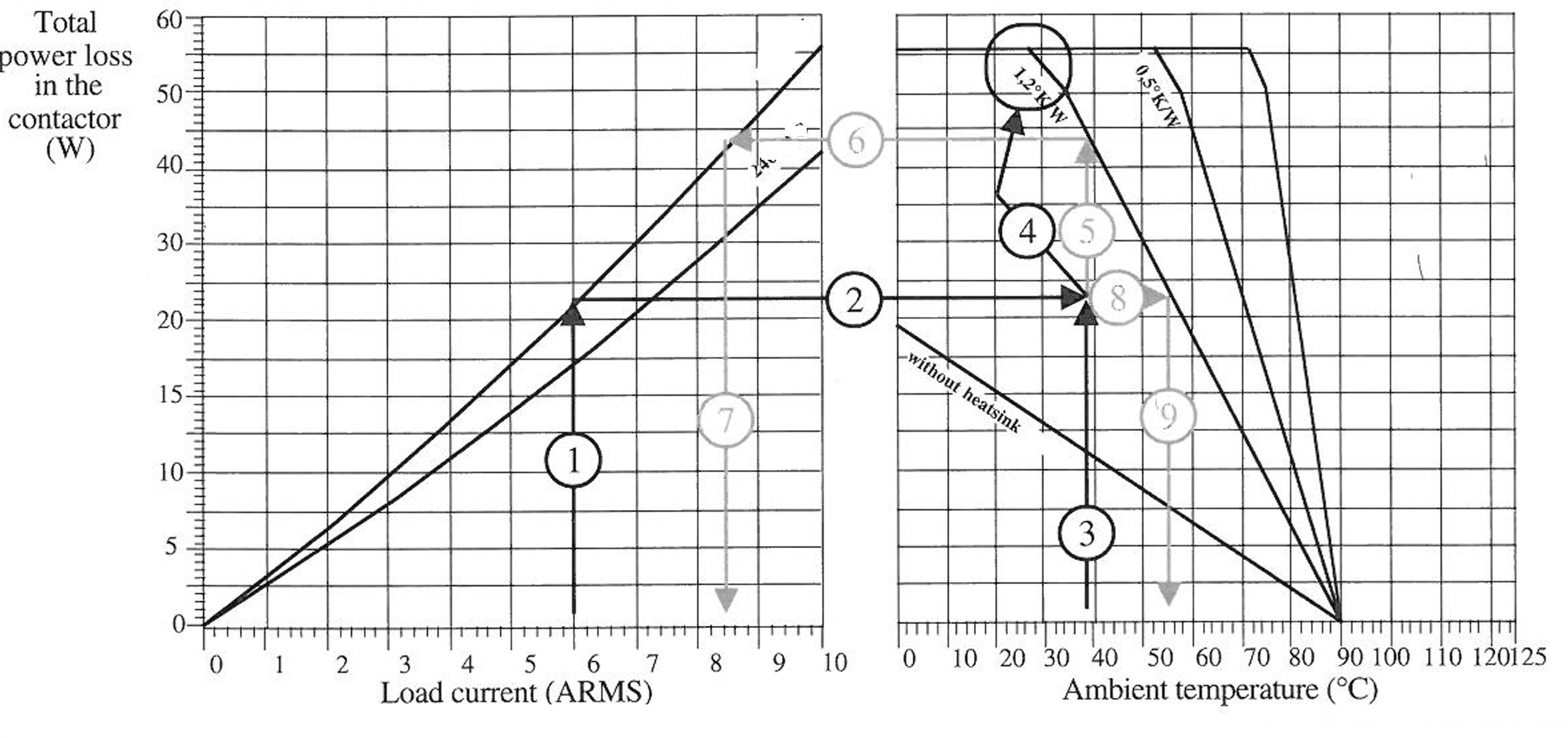
On peut directement déterminer le type de dissipateur à utiliser en fonction du courant commuté et de la température ambiante.
Exemple Ieff = 6 Ampères et température ambiante maxi = 38°C